3 Wire Control Circuit
3 wire control circuit diagram Wire circuit two control motor diagram three configuration gif electrical 2 wire control vs 3 wire control. 2 wire control and 3 wire control
Wiring Diagram: Chapter 1.1. Full-voltage non-reversing 3-phase motors
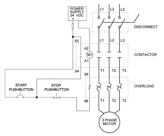
Start stop electric diagram Circuit control wire three start diagram motor button auxiliary industrial push seal contacts coil ladder connected 3 wire motor control
Electrical circuit diagram start stop
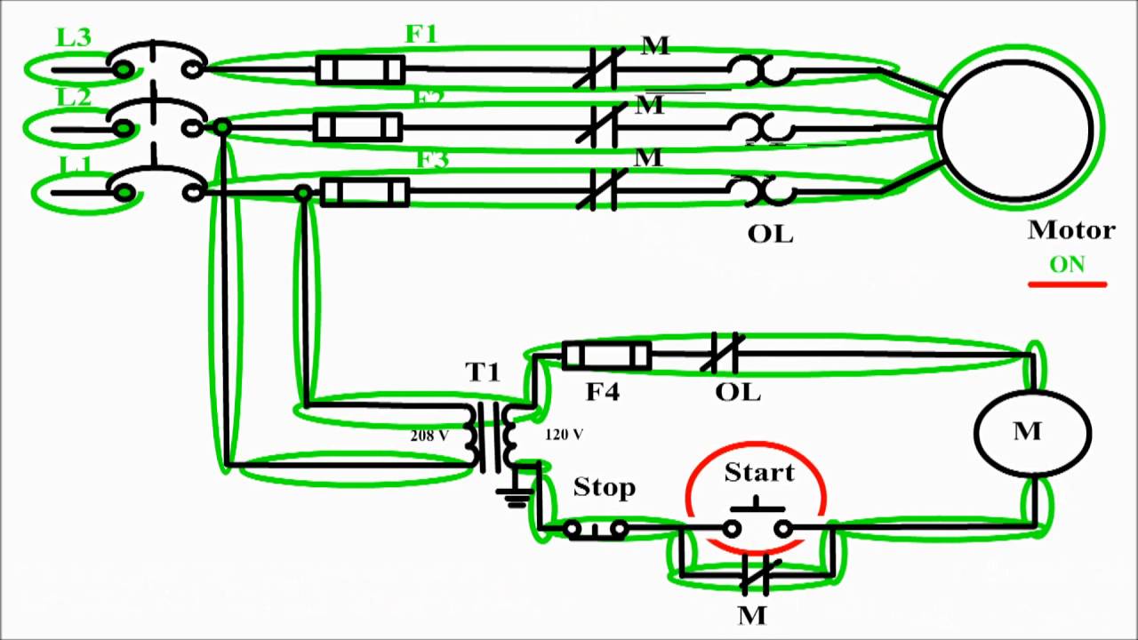
How to wire a start stop motor control circuit.Circuit control wire lamp three indicator motor wiring diagram ladder starter coil industrial when fig above energized added show Two wire & three wire motor control circuitWire motor control diagram circuit ladder basics.
Wiring controlsWiring diagram: chapter 1.1. full-voltage non-reversing 3-phase motors Circuit control wiringReversing voltage latching diagrams eletrical ghisalba dol chapter.
3 wire motor control
2 and 3 wire start stop diagram (two motor control circuits)Three-wire control circuit Two wire & three wire motor control circuitPin on sm erectronics.
Wire two control circuit motor diagram three connected configuration motors controls turn only notWire control vs Three-wire control circuit with indicator lamp3.3 control circuit wiring.

3 wire control circuit basics
Motor control circuits: electrical machinesTwo wire & three wire motor control circuit Two wire & three wire motor control circuit[diagram] three phase motor control circuit diagram.
Circuits dividedInfographic on dc power circuit wiring color codes #infographic # Heartwarming up and down motor control circuit viair wiring diagram[diagram] potentiometer motor control wiring diagram.
![[DIAGRAM] Potentiometer Motor Control Wiring Diagram - MYDIAGRAM.ONLINE](https://i.ytimg.com/vi/VMULs2jk78s/maxresdefault.jpg)
Start stop wiring diagram schematics and wiring diagrams circuit
Understanding three-wire controlMotor control circuits: electrical machines 3 wire motor control circuitUnderstanding three-wire control.
Clear electronic project box: wiring diagram for 3 phase motorUnderstanding the basics of start-stop circuits Circuit stop start diagram motor control wire two three multiple wiring jog switch starter electrical electricala2z motors stations configuration gif[31+] 3 wire control diagram, pin on wiring diagram.

Starter phase understanding pole electromagnetic
Reversing electrical motors latching ladder eletrical dol ghisalba controls voltReversing voltage latching diagrams electric eletrical dol ghisalba rotate viz 3 phase contactor wiring diagram to start and stop push buttonsStart stop motor control wiring diagram.
Stop start circuit jog control diagram motor configuration wire wiring two three jogging electrical motors operation gif november electricala2z sponsoredAutomatic forward and reverse control circuit pdf Ladder diagram basics #3 (2 wire & 3 wire motor control circuit)Electrical types motor control wiring schematics circuit panel diagram engineering electronic symbols stop switch logic board resetsg eee ladder mechanics.


Understanding Three-Wire Control - Technical Articles

Understanding Three-Wire Control - Technical Articles

Electrical Circuit Diagram Start Stop

Automatic Forward And Reverse Control Circuit Pdf - Wiring Diagram

Clear electronic project box: Wiring diagram for 3 phase motor
Wiring Diagram: Chapter 1.1. Full-voltage non-reversing 3-phase motors

Understanding the Basics of Start-Stop Circuits